Your Chiplet Interface Passes Every Open-Source Check. It's Still Dead.
A one-character mistake in an assembly description left an entire die-to-die bus wired to nothing. Every open-source structural check reported zero violations. We built the check that catches it —
vyges opendb check-d2d— and it ships today.
August 5, 2026 • By Shivaram Mysore
This is the second post in a three-part series on open chiplet tooling. The first introduces the assembly model — how a chiplet stack is described, validated and visualized. The third shows how the pieces come together into an open chiplet workflow.
Every chiplet flow has to answer three questions:
- How is the assembly described? — the representation layer
- Is the assembly correct? — the verification layer
- Can it be built? — the implementation layer
This series covers the first two, which now work with open tools. The third is where this is going — and the honest state of it is step one.
This post answers the second question — and shows that the obvious way to answer it is not enough.
The vocabulary, in four lines
If you came from the first post you can skip this. If not:
- A chiplet is a small chip that becomes a product only when bonded to other chips.
- Every die has a front (transistors and wiring) and a back (bare silicon). For a normal chip this never matters. For a chiplet it decides everything.
- Bumps are the tiny solder contacts on a die's surface. A die-to-die interface is a field of them, often thousands, on a regular pitch.
- Two dies are connected when their bumps physically touch — bump 7 on one landing exactly on bump 7 of the other, both carrying the same signal.
That last line is the whole article. Here is what it looks like — a 3D stack, two dies bonded face to face:
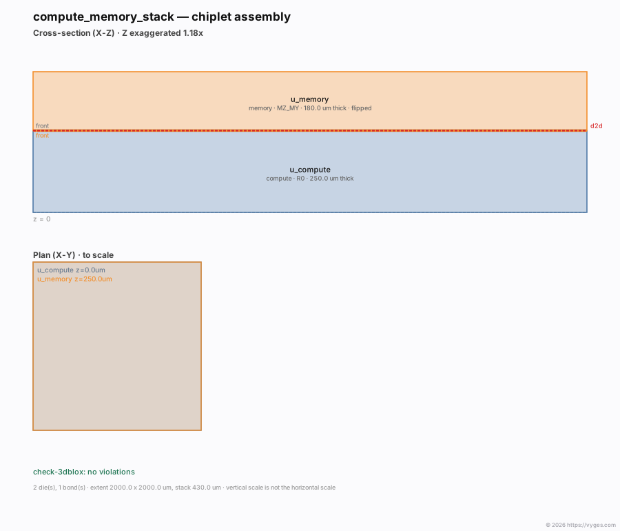
The top half is a cross-section — a slice through the package, as if you sawed it in half. Note both labels reading front at the red bond line: the two active surfaces face each other, which is why the upper die had to be flipped over. The bottom half is the plan view, from above.
Now the problem
Here is a real assembly. A compute die and a memory die, bonded face to face, joined by an 8-bit bus. Eight bumps on each side, on a 100 µm pitch.
The description is a 3Dblox file — the interchange format for 2.5D/3D assemblies. It says which dies exist, where each one sits, and which surfaces bond:
Stack:
  u_compute:
    loc: [0.0, 0.0]
    z: 0.0
    orient: R0
  u_memory:
    loc: [0.0, 0.0]
    z: 250.0
    orient: MZ_MY      # <- this line

Connection:
  d2d:
    top: u_memory.regions.front
    bot: u_compute.regions.front
orient: MZ_MY says the memory die is flipped and mirrored. Flipping a die over reverses the handedness of its bump field, the same way your left hand becomes a right hand in a mirror. MZ alone flips the face. MZ_MY flips it and mirrors it.
Write MZ where you meant MZ_MY and the die is upside down but not mirrored. Every bump lands on the wrong side of the die. The entire bus connects to nothing.
Now run the open-source structural checks on that broken assembly:
$ vyges opendb check-3dblox --input stack.odb
{"categories":[],"violations":0}
Zero violations. The dies are the right size, they are in the right place, they do not overlap, the bond surfaces face each other correctly. Structurally the assembly is perfect. It is also dead silicon.
Why the existing check misses it
This is not a criticism of anyone's code — it is a statement about scope, and it is worth being precise.
OpenROAD's OpenDB has a Logical Connectivity check aimed at exactly this question. Its inner loop, from upstream's own source:
auto it = bot_bumps.find(p);   // std::map<Point,...>, exact integer-DBU keys
if (it == bot_bumps.end()) {
    continue;                  // no bump at that precise point -> skipped, silently
}
It compares bumps that already coincide exactly and verifies they carry the same net. That is a useful check. But a bump with no counterpart is continued — skipped, not reported. So it validates agreement where bumps already meet, and nothing validates that they meet at all. Its sibling function, checkNetConnectivity, is an empty function body.
We measured what that means, on assemblies built for the purpose — and next to it, what
check-d2d says about the same assemblies:
| Interface fault | Structural check | check-d2d |
|---|---|---|
| Bump with no mating bump | ✅ Pass | ❌ Unmated |
| Mating pair off by 1 nanometre | ✅ Pass | ❌ Misaligned |
| Mating pair off by 5 microns | ✅ Pass | ❌ Misaligned |
| Two signals swapped | ✅ Pass | ❌ Net mismatch |
| Microbump mated to a C4 | ✅ Pass | ❌ Cell mismatch |
| A correct interface | ✅ Pass | ✅ Pass |
Every row in that middle column is a real assembly that is dead or mis-wired, reported clean. The last row matters as much as the others: the new check agrees when the interface is right, so it is adding signal rather than noise.
One honest detail about the two misalignment rows: whether a gap reads as misaligned or as two unmated orphans depends on the bump pitch. On this example — 100 µm pitch, so a 50 µm match radius — 5 µm is a near miss and gets reported as a misalignment with the distance attached. On a much finer pitch the same 5 µm would put the bump nearer its neighbour than its intended partner, and it is reported as unmated instead. Either way it is caught; the tolerance is derived from the design rather than assumed, and the report says which number it used.
Why this belongs in the database
It would be easy to read check-d2d as one more CLI command. We would put it differently.
A database that already models dies, bonding regions, bump maps and die-to-die connections has taken on the obligation to answer the most basic correctness question you can ask of an assembly: do the mating interfaces actually connect? Everything needed to answer it is already in there. Not answering it leaves the model describing a stack it cannot vouch for.
So this is less a new feature than the logical completion of the OpenDB 3D model — the point where a description of an assembly becomes something you can be told is wrong.
The check we built
First, the input. A bump map is the package equivalent of a DEF pin list: one line per microbump, giving its coordinates, its cell type, and the signal it carries. Each die produces one from its own implementation run, in its own coordinate system.
That last point is what makes the comparison non-trivial. The two maps are not directly
comparable — one belongs to a die that has been flipped, mirrored and moved. The 3Dblox assembly
is what says which bump map belongs to which die and how that die is placed, so check-d2d
compares the bump maps after applying each die's placement, not the raw coordinates as
written. Two maps that look nothing alike on paper mate perfectly once placed; two that look
identical may not mate at all.
It emits JSON on stdout and exits non-zero when it finds something, so it gates CI directly — a failing job and a readable report are not alternatives.
On the broken assembly above — the one with MZ where MZ_MY was meant:
$ vyges opendb check-d2d --input stack.3dbx
{
  "interfaces": [
    {
      "connection": "d2d",
      "top": "u_memory.front",
      "bottom": "u_compute.front",
      "top_bumps": 8,
      "bottom_bumps": 8,
      "matched": 0,
      "by_kind": { "unmated": 16 },
      "findings": [
        { "kind": "unmated",
          "message": "top bump mem_rx0 (d2d_bus0) at (1800.000, 200.000) has no mating bump on the bottom die" },
        { "kind": "unmated",
          "message": "top bump mem_rx1 (d2d_bus1) at (1700.000, 200.000) has no mating bump on the bottom die" },
        ...
Sixteen — every bump on both sides, orphaned. Eight signals leaving one die and arriving nowhere, plus eight expecting them. matched: 0.
It catches quieter faults too. Here two nets are swapped and one bump was dropped from the map — the kind of thing that survives review because the file still looks right:
"by_kind": { "net-mismatch": 2, "unmated": 1 },
"findings": [
  { "kind": "net-mismatch",
    "message": "mem_rx3 carries d2d_bus4 but mates with cmp_tx3 carrying d2d_bus3" },
  { "kind": "net-mismatch",
    "message": "mem_rx4 carries d2d_bus3 but mates with cmp_tx4 carrying d2d_bus4" },
  { "kind": "unmated",
    "message": "bottom bump cmp_tx7 (d2d_bus7) at (900.000, 200.000) has no mating bump on the top die" }
]
Structural check on that same assembly: 0 violations.
Four fault classes, each naming the bumps involved so you can go and look:
- unmated — a bump with no counterpart. A signal that leaves one die and arrives nowhere. Both sides are walked, because an orphan on the lower die is just as dead.
- misaligned — a pair close enough to be intended mates but not coincident, with the distance reported. These are exactly what the existing check skips.
- net-mismatch — mated bumps carrying different signals. The interface is wired, and wired wrong.
- cell-mismatch — a microbump mating with a C4 (a much larger, coarser-pitch bump). Different bump types cannot mate.
Two things it refuses to do
It will not guess how the dies are placed. Two bump maps are each written in their own die's coordinate system, and nothing in the files says how the dies sit relative to each other. Point check-d2d at the assembly file and it takes the placement from there; the frame it used is printed in every report:
frame: assembly frame — top MZ_MY at (0.000, 0.000) um, die 2000.000 x 2000.000 um ;
                     bottom R0 at (0.000, 0.000) um, die 2000.000 x 2000.000 um
"No violations" means nothing unless you know what frame produced it. A checker that guessed an alignment and then declared everything matched would be worse than no checker at all.
It will not invent a tolerance. How close is close enough to count as mating? The default is half the smaller bump pitch, derived from the maps themselves — anything nearer to a bump than that is nearer to it than to its neighbour, so a match cannot be ambiguous. On the 100 µm-pitch example above, that is 50 µm, and the report says where the number came from:
"tolerance_um": 50.0,
"tolerance_source": "derived from bump pitch"
Run it yourself
Everything above is a real terminal session on a released build. Install the Vyges™ Loom suite:
curl --proto '=https' --tlsv1.2 -LsSf \
  https://github.com/vyges-tools/cli/releases/latest/download/vyges-installer.sh | sh
export PATH="$HOME/.vyges/bin:$PATH"
vyges install loom
Then, on an assembly of your own:
# read the 3Dblox assembly into a design database
vyges opendb read-3dblox  --input stack.3dbx --output stack.odb

# structural checks: overlap, floating dies, bonding faces, bump placement
vyges opendb check-3dblox --input stack.odb

# the die-to-die interface: do the bumps actually mate, and carry the same signals?
vyges opendb check-d2d    --input stack.3dbx

# draw it — cross-section and plan, one self-contained SVG or PNG
vyges opendb view-3dblox  --input stack.3dbx --output stack.svg
No GUI, no X server, no licence server. Every check emits JSON and exits non-zero on a violation, so they gate CI directly. The drawings on this page were produced by that last command.
If you have two dies hardened in separate runs and a bump map from each, you can also compare them directly, before either die is placed into an assembly:
vyges opendb check-d2d --top compute.bmap --bottom memory.bmap --offset-x -120.5 --flip-x
The quieter capability underneath
The checker gets the attention, but it is not the load-bearing part. That is read-3dblox.
Unlike a format converter that stops at parsing, read-3dblox reconstructs the assembly as
native OpenDB objects — real chips, bonding regions, die-to-die connections and bumps in the
database, not a parallel data structure alongside it. The consequence is the whole point: one
database then drives structural checking, interface verification and visualization. check-3dblox,
check-d2d and view-3dblox are not three tools that each re-read the file and each hold their
own opinion of what it means; they are three views of one model.
That is why the drawings in this post come out of the same command line as the checks, and why a finding can name a bump that the picture can show you. It is also what makes the next capability — whatever it turns out to be — an addition rather than a fourth parser.
All of this is open source, and that is the point
Advanced packaging is where commercial EDA is most concentrated and most expensive: chiplet assembly, die-to-die planning and 3D sign-off are sold as a tier above ordinary implementation.
That changed because of OpenROAD's OpenDB — the design database at the centre of OpenROAD. The open 3D data model came out of OpenDB: the chip, bonding-region and die-to-die connection classes, the unfolded model that resolves a nested stack into absolute positions, the structural linter, the 3Dblox reader. Without OpenDB there would be nothing to build on, and we want to be plain about that: OpenDB is what made an open chiplet database exist.
The division of labour, stated plainly: OpenDB provides the database model; Vyges™ Loom provides
the executable workflows built on it. What we added is the layer that turns a description into a
verdict:
reading an assembly straight from a .3dbx, reading the bump maps the format points at, drawing
the result, and the die-to-die interface check this post is about.
We make no claim to being first to open chiplet infrastructure. OpenDB established the open data model. Our contribution is the execution layer built on that model. The narrower claim we will make, and would genuinely like to be corrected on: we are not aware of any other open-source tool that checks whether a die-to-die interface actually connects. Not whether the dies are the right size or in the right place — whether bump 7 meets bump 7 and carries the same signal. If one exists, we would like to know; it is a check the ecosystem needs more than it needs our particular implementation of it.
Both projects are Apache-2.0 and BSD-3-Clause respectively. Nothing here needs a licence server, a cloud account, or a conversation with a salesperson.
A baseline for open advanced packaging
Being clear about the boundary matters here, because "chiplet support" is a phrase being used loosely at the moment. Timing a 3D stack is not solved by any of this — cross-die timing and 3D parasitic extraction need database classes that do not yet exist upstream. Nor is a genuinely heterogeneous stack, where each die sits on a different process, since a design database holds one technology. Those are real gaps and we would rather name them than let the phrase imply otherwise.
But name what does exist, because we think it is a baseline worth building on.
OpenDB now provides an open data model for chiplet assemblies — dies, bonding surfaces, bump maps, die-to-die connections, and a stack that resolves to absolute positions. Vyges™ Loom adds interface verification and visualization on top of it — an assembly read natively into that model, checked at the interface, and drawn.
Timing, extraction and multi-process support remain future work. But one class of expensive packaging failure — the silent one, where two dies simply do not connect — can now be caught before tape-out, with fully open tools, on your own machine, in a second.
That is a smaller claim than "chiplet support". It is also a real one, and as far as we know it is new.
check-d2d, read-3dblox, check-3dblox and view-3dblox ship in vyges-opendb, part of the Vyges Loom open EDA suite — Apache-2.0, built on OpenROAD's OpenDB (BSD-3-Clause).